
The Wisdom of Convention Awaits
I have argued that RCM analysis is a costly impediment to progress for most plants and most equipment. The next question is how does a maintenance organization determine what best practice scope and interval should be?
The answers are readily available in published documents. Many of them have been around for decades. Most of them ignored.
The perfect is the enemy of the good. 85% of RCM analyses are not implemented, and the other 15% vary in quality. With these sorts of numbers, RCM is the enemy of the any. Almost nothing good happens for the majority of plants trying it. This post shows the path to good for rotating, instrument, and electrical equipment. Fixed equipment operates under separate regulatory inspection regimes and integrity management frameworks (API 510/570/653, RBI per API 580/581, and applicable jurisdictional codes) that set intervals by corrosion rate, consequence, and code requirement rather than reliability analysis; those programs are not addressed here.
As you read through this, you may find some of this obvious. Ask yourself, then why do we need RCM for most equipment? And why haven’t all these standards and guidance been collected and applied more effectively over the past four decades?
See our practitioner library for the next level of detail:
Rotating Equipment
If you asked an experienced, reliability-minded technician what a general interval should be for formal online inspection of rotating equipment – especially given a good operator rounds program – the most likely answer would be “quarterly.” They’d recommend an annual offline inspection and would tick off the things to look for. Lubrication would be more variable based on equipment specifics. Condition-monitoring routes every two or three months.
They wouldn’t say, “I dunno, pay for an analysis.” And if you told them what an RCM analysis cost, they would think management is even more lost than they already do. The wise ones might say, “You know we could do some real reliability improvements with that money.”
The technician’s answers align to best practice guidance published in a number of places and that guidance aligns remarkably well to what you would get out of an RCM process working off of failure modes, P-F intervals, and the like.
This, in turn, aligns to the argument that RCM isn’t wrong, but that it is the wrong methodology for most equipment, because it unnecessarily re-derives what is already known.
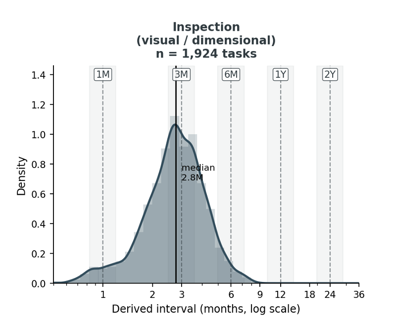
The technician and the “rules of thumb” recommend a quarterly visual as a baseline. I modeled the population-level distribution of recommended visual inspection task intervals indicated by FMEA P-F interval, and it output a median of 2.8 months, with a long left tail covered by operator rounds. This is the image at the top.
The model suggests a 1.6-month interval for vibration, and 3.5 months for oil analysis. There’s an argument to be made that shorter interval failure modes like imbalance could be caught by operator rounds and you could safely go to a 2-month interval for most equipment. This again mirrors good practice conventional wisdom.
If you apply these intervals and provide good execution references that define the acceptance criteria and action levels, you have a far better and more executable PM program than what comes out the far end of most RCM adventures.
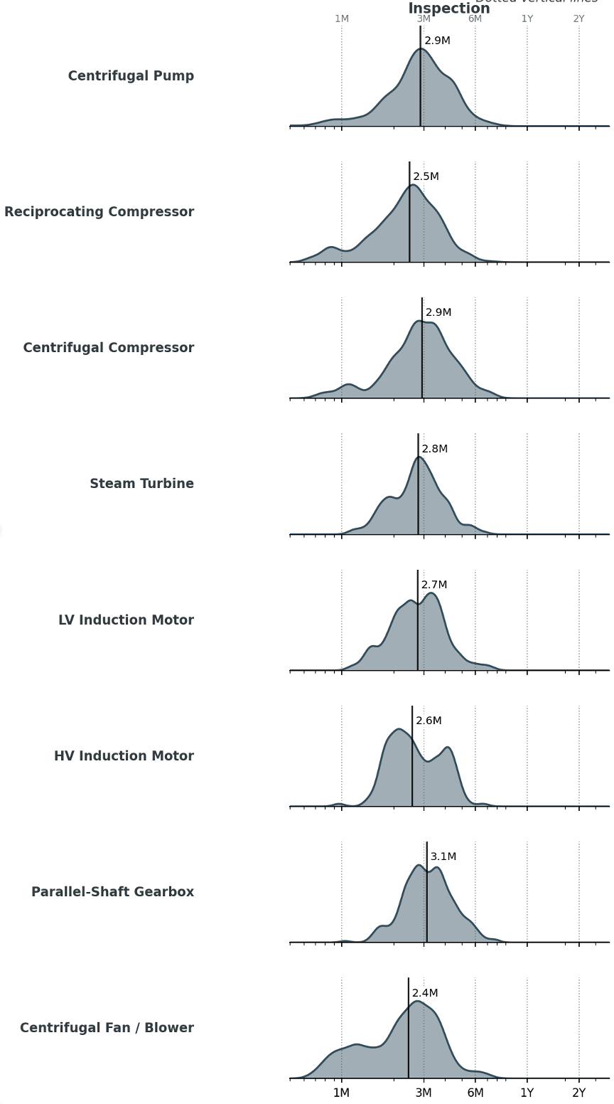
The distribution does not change significantly for most rotating equipment types. Narrowing the interval to two months for critical equipment and/or harsh services is as easy as it sounds. For problem equipment you should already have failure data to help narrow the interval appropriately and indicate additional work. Now take the analytical effort saved, invest most of it in a proper execution framework, to include condition monitoring, and the rest in the bit of analysis warranted for truly exceptional equipment and operating contexts.
The point here is not to advocate a quarterly set it and forget it interval. The point here is to deploy and discover. Take a solid quarterly baseline, modify it for your special equipment, and spend 18 months dialing it in based on real data rather than 18 months doing RCM before deploying. The same modeling mentioned above, split by equipment types, suggests how interval optimization would play out. The difference is how quickly you start making an impact.
Lubrication Calculation
Lubrication is a separate consideration, but can be handled in a similarly common-sense way.
SKF attributes roughly 36% of premature bearing failures to lubrication problems. Over‐pressurization from excess grease — which destroys seals, raises operating temperature, churns the lubricant, and accelerates oxidation — sits at the top of that subset. A grease gun on a quarterly route, applied without quantity or class guidance, kills bearings as surely as no greasing at all.
Grease intervals come from the SKF relubrication-interval diagram, published in the SKF General Catalogue and reproduced in equivalent form in every major bearing manufacturer's engineering handbook (Schaeffler/FAG, Timken, NSK). In plain terms: a 1,800 rpm motor with a 75 mm outside-diameter deep-groove ball bearing earns a baseline interval of 6,000–8,000 operating hours — eight to twelve months in continuous service — under clean, cool, horizontal conditions.
Four modifiers stack on top of that baseline. Every 15°C above 70°C bearing temperature halves the interval. Vertical orientation halves it again. Severe contamination halves it again. High vibration halves it again. Bearing type applies an additional multiplier to the interval: cylindrical and needle roller bearings use 0.5×; spherical roller and tapered roller bearings use 0.2× (requiring roughly five times more frequent regreasing than radial ball bearings). Cylindrical and spherical roller thrust bearings also use 0.5×. The math is multiplicative.
One or two modifiers in normal service collapses the same bearing to quarterly. Three or four in hot, dirty, outdoor service collapses it to six or eight weeks. Most plant equipment hits one or two modifiers and lands quarterly. A minority — clean, cool, horizontal, deep-groove ball — runs annual or longer.
Use an ultrasonic grease gun. Over-greasing kills more bearings than under-greasing. Spend the money on the gun, not on RCM.
Oil is different. Sump and circulating oil charges fail by oxidation, additive depletion, and contamination ingress — none of which respect a calendar. The standards reflect that. ASTM D4378 (turbine oil) and ASTM D6224 (auxiliary equipment) prescribe condition-based change-out triggered by acid number rise (typically +0.3–0.4 mg KOH/g over new), viscosity drift (±5% change from initial as a warning threshold, ±10% as alert/condemn, at 40°C per ASTM D4378), water content (>0.1% in turbine service), and particle count against ISO 4406 cleanliness targets — 18/16/13 for gear oils, 16/14/11 for hydraulic. Range by application: API 614 lube and seal consoles for special-purpose machinery run 3–7 years on continuous filtration with quarterly to semi-annual sampling; centrifugal pumps and recips per API 610 and API 618 defer to OEM, with bath oil typically 12 months clean and 3–6 months hot or contaminated; industrial gearboxes per AGMA 9005-F16 run 6–12 months on mineral oil and 2–3 years on synthetic PAO or PAG; reciprocating compressor cylinder feeds run continuous, with crankcase oil on the same condition-monitoring framework as other sumps. The principle: condition-direct anything you can sample. Calendar-change only the small simple sumps where the sample costs more than the oil.
The unifying principle is the same across both. A calculated baseline — SKF curve for grease, OEM default plus ASTM trigger limits for oil — sets the starting interval. Four severity factors recur across every standard and adjust it: temperature, contamination, load, and orientation. The intervals in the distribution aren't arbitrary buckets and aren't purely time-directed. They're time-directed baselines with a condition-monitoring overlay. That is what the data is showing when the lubrication distribution clusters at 6 months for motor grease, 12 months for sump oil, and 24 months for big API 614 consoles: each cluster is the calculated baseline for that lube system class under standard service, and the spread within each cluster is the modifier stack acting on individual instances.
Electrical
Two documents run electrical PM in U.S. industrial facilities.
NFPA 70B changed materially in 2023 when it was converted from a recommended practice to a standard, replacing “should” language with “shall.” The current edition is NFPA 70B-2026. The important shift remains: electrical maintenance is no longer a “good idea” document written in soft recommendation language. NFPA 70B is not automatically law in every facility, but where adopted by a jurisdiction, incorporated into company or insurance requirements, or cited as evidence of recognized electrical-maintenance practice, ignoring it becomes significantly harder to defend. The standard introduced an Equipment Condition Assessment that sets intervals as a function of physical condition, criticality, and operating environment — the same principle as the rotating‐equipment configuration matrix, applied to electrical assets.
NETA MTS — the International Electrical Testing Association’s Maintenance Testing Specifications — is the testing standard. Where NFPA 70B says “test the breaker,” NETA MTS specifies the test, the acceptance criterion, and the documentation. The two are complementary. NFPA 70B sets the interval framework. NETA MTS specifies the test.
IEEE specialty standards fill in for transformers (C57.106 for oil, C57.152 for testing), batteries (450 for vented lead‐acid, 1188 for VRLA), cables (400 series for diagnostic), and grounding (81 for resistance measurement).
Most plants have not implemented either NFPA 70B or NETA MTS as their formal PM specification. The intervals are written. Most plants ignore them. The shift to Standard status in 2023 — now carried forward in NFPA 70B-2026 — means that ignoring them in adopting jurisdictions or where the standard is cited as recognized practice invites citation. This has not penetrated most electrical PM programs.
There are several major PM-draw categories in industrial electrical programs.
Switchgear and motor control centers (LV and MV) are covered by NFPA 70B Chapters 15 and 17 and NETA MTS §7.5, directing annual thermography and visual, three-year functional and insulation tests.
Electric motors fall under NFPA 70B Chapter 12 and IEEE 43: annual insulation resistance and thermography, with surge testing and power factor on critical machines at three-to-five-year cycles. The mechanical aspects of the motor follow the rotating equipment guidance above.
Variable frequency drives are addressed by NFPA 70B Chapter 22: annual visual and thermography with cooling and capacitor checks; firmware and DC bus capacitor review at three years.
Transformers (oil-filled) follow NFPA 70B Chapter 11 and IEEE C57.106: annual dissolved gas analysis and moisture sampling, full electrical testing including power factor at three-to-five years.
UPS systems and battery banks follow NFPA 70B Chapter 17, IEEE 450 (vented lead-acid), and IEEE 1188 (VRLA): monthly visual, quarterly impedance or load voltage checks, annual capacity test.
Emergency generators are governed by NFPA 110: weekly inspection, monthly exercise under load (≥30 minutes per NFPA 110 §8.4), annual major service with load-bank testing where monthly load conditions are not routinely met. The reference table at the end of this article lists primary sources and default intervals for each class.
Instrumentation
Instrumentation has three regimes, plus control valves. Each has a distinct authority. Each has a distinct interval logic. Conflating them produces non‐compliant programs.
Safety Instrumented Systems: Anything classified as a safety function under IEC 61511 has a proof‐test interval calculated from the SIL target, the demand rate, and the dangerous‐undetected failure rate of each component. ISA‐TR84.00.03 is the maintenance technical report that operationalizes 61511 for U.S. process industry use. Proof‐test intervals typically run 1‐5 years. Skipping or extending a proof test on an SIS function without re‐running the calculation is a PSM citation waiting to happen.
Process calibration: For instruments not SIS‐classified — most pressure, temperature, level, and flow loops in the plant — calibration interval comes from manufacturer drift specification, criticality of measurement, and (in many shops) the ISA RP 5.1 / API 551 documentation tradition. NIST traceability is required. Annual on critical, two to three years on standard service is recommended.
The industry tends to calibrate far too frequently. Monthly or quarterly calibration of stable, process-hardened instruments is widespread in refineries and chemical plants, driven by a misapplied intuition that more maintenance equals more reliability. Every calibration event is a physical intervention: technicians disconnect signal leads, disturb terminal connections, apply test pressure or signal, and reconnect. Each of those steps is an opportunity to introduce the failure you were trying to prevent. A loop that had been sitting stable for eighteen months comes back from its monthly calibration with a ground fault or a noisy signal. The act of checking becomes the dominant failure mode. Unless drift history, process criticality, or a regulatory requirement specifically justifies a shorter interval, default to annual or longer and let stable instruments run.
Custody transfer and emissions: These come with prescriptive intervals. API MPMS Chapters 5 and 14 govern hydrocarbon custody measurement. AGA Reports 3, 7, 9, and 11 govern natural gas. EPA 40 CFR Parts 60 and 75 govern continuous emissions monitoring. Intervals are not negotiable. Documentation is audited. Penalties are real.
Control valves are among the highest-volume PM draws in any instrumentation program and are frequently under-maintained. ISA-RP75.18 and API 553 govern stroke testing and maintenance; FCI 70-2 specifies seat leakage classification. Annual partial stroke tests on critical valves, bench tests at three-to-five years. SIS-classified shutdown valves carry a proof-test interval derived from the IEC 61511 calculation — not the annual default. Emergency isolation valves (EIVs) and blowdown valves follow the same logic. The most common maintenance gap is treating all control valves as equivalent when the SIS-classified ones carry entirely different obligations. A secondary gap is neglecting the positioner and its feedback signal — valve PM that only strokes the body without verifying positioner calibration misses the failure mode that causes the most spurious trips.
Two Worked Examples
Two pieces of equipment, every operation traced to a published source. This is what “deploy what’s already written” looks like in practice.
P‐1105: Quarterly PM, Sources Cited
P‐1105A/B is a Flowserve Durco Mark III 3×4‐13 horizontal centrifugal pump in Naphtha Stripper Reflux service at the Eastport refinery’s Crude Unit 2. Light naphtha at approximately 350°F. 150 HP LV motor, John Crane Type 1 single seal with API Plan 11 flush, oil‐mist lubricated bearings.
Configuration matrix assignments: Driver_Type = LV Motor. Lube_Configuration = Oil Mist. Sealing_Configuration = Mechanical Seal (Plan 11). Lubrication_Class = G3 (motor is 150 HP, n = 3,600 rpm — above the threshold). Oil_Class = N/A on motor (oil mist), O3 on pump bearing housings (oil‐mist supplied, but with annual non‐intrusive oil change verification per OEM).
Quarterly PM — six operations after safety review and before completion verification — with every operation traceable to a published source.
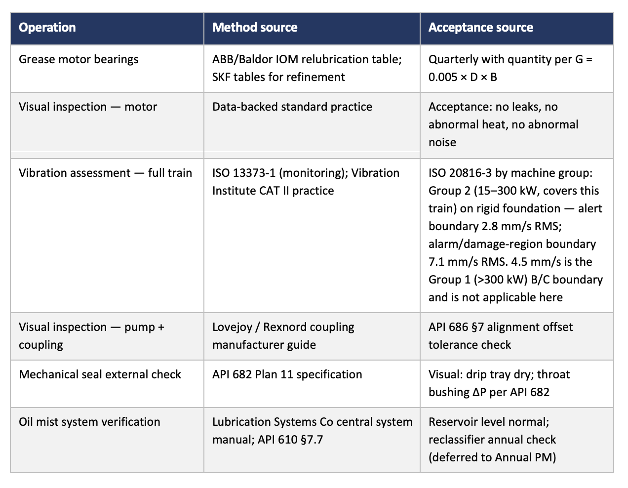
Total analytical content required to build this Quarterly: zero. Total lookup time: a couple of hours, once, for the whole pump class. Total recurring effort: confirming applicability per FLOC in the configuration matrix.
Compare to an RCM workshop on the same pump: two days, ten participants, 40–80 failure modes enumerated, decision logic applied, tasks selected. Output: tasks that closely mirror the API and ISO references already specify, with most never reaching the work order.
M‑2208: Annual Electrical PM, Sources Cited
M‑2208A is a 500 HP, 4160 V squirrel-cage induction motor in critical crude charge pump service at the Eastport refinery’s Crude Unit 2 — the driver for P-2208A, an API 610 BB3 multistage pump in continuous crude preheat train service. NEMA Design B, 1,800 rpm, WP-II enclosure, A/B hot-standby pair. Last rewound 2019 at an EASA-certified repair facility with rewind records on file.
Configuration matrix assignments: Voltage_Class = MV (4160 V). Enclosure = WP-II. HP_Class = 500. Criticality = A (loss of either motor takes the crude unit offline). Electrical_PM_Class = E3 (MV critical service — annual full electrical PM per NFPA 70B and NETA MTS).
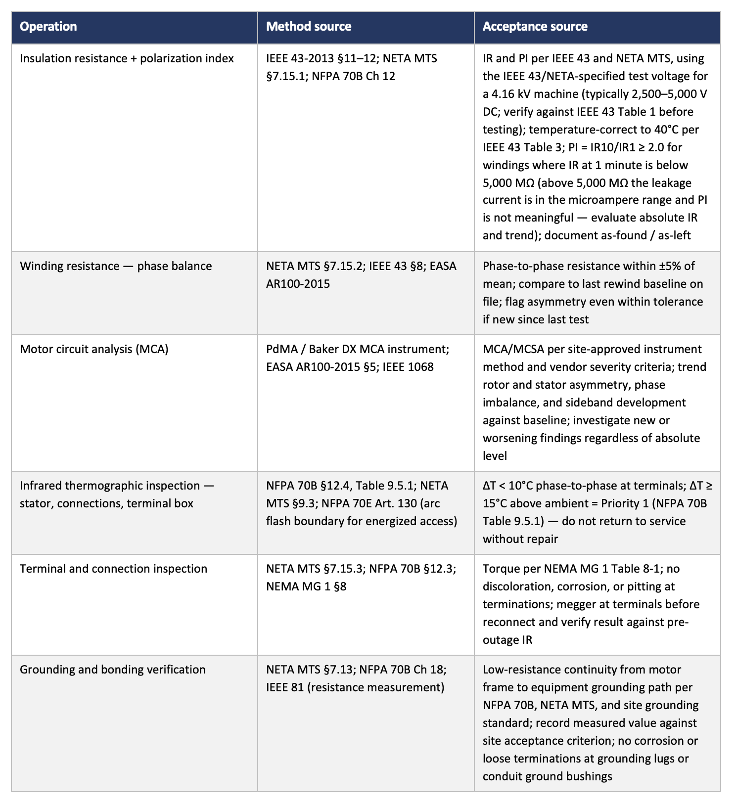
Annual electrical PM — six operations — with every operation traceable to a published source. (The mechanical PM for the motor would be derived like the example above)
Total analytical content required to determine this PM: zero. The voltage class, enclosure type, HP, and criticality rating determine the test set from NFPA 70B Chapter 12 and NETA MTS §7.15. The acceptance criteria are published in IEEE 43 and NETA. No RCM workshop touches any of this. What does fall apart in practice is not the test selection — it is the absence of trending. Each year’s IR result looks acceptable in isolation. The drift from 800 MΩ to 80 MΩ over four years is invisible without the history, and that history disappears when the paper test sheets do. An annual electrical PM that does not produce a permanent trending record produces half the value it should.
Across a refinery’s rotating, instrument, and electrical populations, the share of equipment in genuinely novel service runs 1–5%. Everything else is a deployment problem, not an analysis problem. Treat it accordingly.
See our practitioner library for the next level of detail: